Welcome to Engineers' Forum

CSI Bridge V15.1 (New MF link)

Unknown | 23:28 | 0 nhận xét
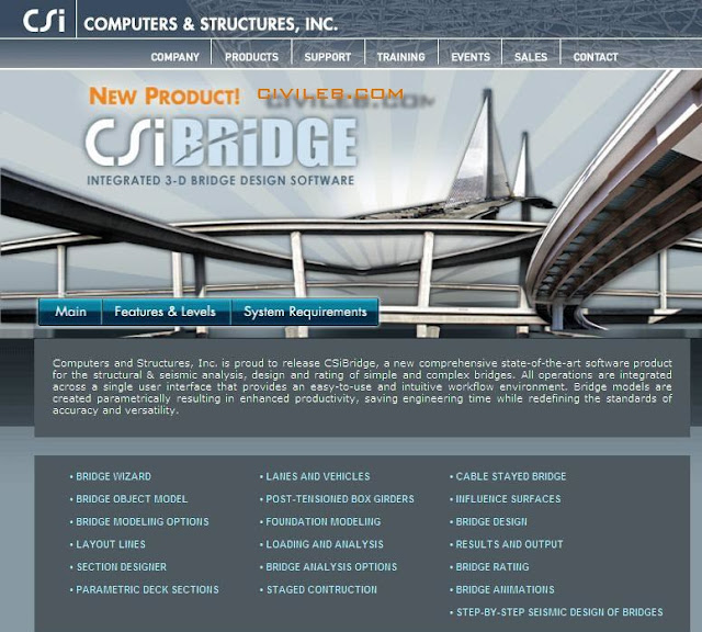
Computers and Structures, Inc. is proud to release CSiBridge, a new comprehensive state-of-the-art software product for the structural & seismic analysis, design and rating of simple and complex bridges. All operations are integrated across a single user interface that provides an easy-to-use and intuitive workflow environment. Bridge models are created parametrically resulting in enhanced productivity, saving engineering time while redefining the standards of accuracy and versatility.
Image


Cra**k:

Mediafire unlock password: nhawe

System Requirement
Processor:
• Minimum: Intel Pentium 4 or AMD Athlon 64.
• Recommended: Intel Core 2 Duo, AMD Athlon 64 X2, or better.
• A CPU that has SSE2 support is required.
• The SAPFire® Analytical Engine includes a multi-threaded solver that can take advantage of multi-core CPUs.

Operating System:
• Microsoft® Windows XP with Service Pack 2 or later, Microsoft® Windows Vista, or Microsoft® Windows 7, 32- and 64-bit versions.
• With a 64 bit operating system, the SAPFire® Analytical Engine can utilize more than 4 GB of RAM, making it possible to more efficiently solve larger problems.

Memory:
• Minimum: 2 GB for XP O/S, 4 GB for Vista/Windows 7 O/S.
• Recommended: 4 GB for 32-bit O/S, 8 GB or more for 64-bit O/S.
• The problem size that can be solved & the solution speed increases considerably with more RAM.
• Vista/Windows 7 requires more RAM than XP for the operating system itself.

Disk Space:
• 6 GB to install the program.
• Recommended: 500GB or larger Hard Disk Drive (7200 rpm SATA)
• Additional space required for running and storing model files and analysis results, dependent upon the size of the models.

Video Card:
• Minimum: Supporting 1024 by 768 resolution and 16 bits colors for standard (GDI+) graphics mode.
• Recommended: Discrete video card with NVIDIA GPU or equivalent and dedicated graphics RAM (512 Mb or larger) for DirectX graphics mode. The card must be DirectX 9.0c compatible (DirectX SDK Aug 2009 – Build 9.27.1734.0).
• DirectX graphics mode fully utilizes the hardware acceleration provided by a GPU and dedicated graphics RAM.
• For better graphics quality in terms of anti-aliasing and line thickness, the device raster drawing capabilities should support legacy depth bias

CSI SAP2000 V15.1.0_Full Cr@ck [MF]

Unknown | 00:00 | 0 nhận xét
[Image: IS_sap.jpg]

Supported Operating Systems: Windows XP, Windows Vista & Windows 7
Newer Features
The following list identifies changes made to the program since the prior release:
More responsive graphical user interface, especially for the use of database tables
Real-time analysis for smaller models
Quick and easy generation of final printed reports
Predefined reports, or fully user-customized reports
Cover sheet
Formatted tables of model definition, analysis and design results
Graphical displays
Detailed design sheets
Improved automated load combinations for design
AISC 360-05/IBC2006 steel-frame design code, with seismic provisions
Direct Analysis Method of AISC 360-05 code
Includes small P-delta effect
Automated inclusion of stiffness modification factors, with user control
Design-decision guidance on when Direct Analysis Method is needed
CAN/CSA-S16-01 steel-frame design code, with seismic provisions
Enhanced design of eccentrically braced frames for AISC 360-05/IBC 2006 and CAN/CSA-S16-01 steel-frame design codes
Canadian NBCC 2005 wind loads, seismic loads, and response-spectrum functions
Load combinations can be converted to nonlinear load cases for advanced design
Enhanced display of failure modes for steel-frame design
DirectX graphics
Hyperstatic analysis for secondary prestress forces
Staged construction enhancement
Control by individual objects as well as by group
Frame end releases can be changed
Property modifiers for frames, tendons, and shells can be changed
Section properties for frames, tendons, and shells can be changed
Enhanced Section Designer
More control over material properties, including Mander model for all sections
Overlapping shapes allowed
Improved Boolean operations
Frame element fiber hinges for arbitrary sections can be defined using Section Designer
External tools developed by dealers and third parties can be accessed in SAP2000
OpenAPI functionality is complete and available without additional license
Users can add their own documents to be accessed through the SAP2000 Help menu
Export of geometry and element connectivity to CSI Perform-3D
Enhanced import of STAAD models

MODELING (A, P, B)
• Object Based Graphical Interface
• Model Templates with Auto Meshing
• Frame, Cable and Tendon Members
• Area (Shell) and Solid Objects with Internal Meshing
• Integrated Graphical Section Designer for Complex Frame Shapes
• Bridge Wizard for Bridge Modeling (A, P, BR)
• Editing with Move, Merge, Mirror and Replicate
• Accurate Dimensioning with Guidelines and Snapping
• Auto Edge Constraints for Mismatched Shell Meshes
• Quick Draw Options for Object Creation
• Tendons in Frame, Shell and Solid Objects
• Parametric Bridge Cross Sections (A, P, BR)
• Support for Multiple Coordinate Systems
• Powerful Grouping and Selection Options
• Definition of Highway Layout Lines (A, P, BR)
• Automatic Generation of Code Lateral Wind and Seismic Loads
• Wind Loads on Open Structures
• Transfer of Loads from Area Objects to Framing Systems
• Application of Lane Loads to Bridge (A, P, BR)
• Cracked Properties – Property Modification Factors
• Gravity, Pressure and Thermal Loading
• Line and Surface Multi-Linear Springs (A)
• Staged Construction Analysis (A, SC)
• Wave Generator (A, OS)
• Parametric Tendon Layout for Box Girders (A, P, BR)

SAP2000 ANALYSIS
• Static Analysis with Frame and Shell Objects (A, P, B)
• Response Spectrum Analysis with Eigen or Ritz Vectors (A, P, B)
• P-Delta Analysis (A, P, B)
• Joint Constraints including Rigid Bodies & Diaphragms (A, P, B)
• Applied Force and Displacement Loading (A, P, B)
• Gravity, Pressure and Thermal Loading (A, P, B)
• Layered Shell Element (A, P, B)
• Post Tensioning in Frame, Area and Solid Objects (A, P, B)
• Relaxation & Anchorage Slip Losses in Tendons (A, SC)
• Plane, Asolid and Solid Objects (A, P)
• Time History Analysis, including Multiple Base Excitation (A, P)
• Frequency Domain Analysis – Power Spectral Density (A, P)
• Moving Loads (A, P, BR)
• Time Dependent Concrete Creep & Shrinkage Effects (A, SC)
• Frame Hinges for Axial, Flexural, Shear & Torsional Behavior (A)
• Nonlinear Static Pushover Analysis (A)
• Viscous Dampers (A)
• Fiber Hinges (A)
• Base Isolators (A)
• Gap Object for Structural Pounding (A)
• Time History with Wilson FNA or Direct Integration Methods (A)
• Dynamic Effects of Moving Loads (A, P, BR)
• Segmental Construction Analysis (A, SC)
• API Simplified Fatigue Analysis (A, OS)

BUCKLING
• Buckling Analysis Around Any Nonlinear State (A)
• Element-Based P-Delta Effects for Local Buckling Instabilities (A)

LARGE DISPLACEMENTS
• Large Displacement/Small Strain Analysis (A)
• Nonlinear Large Rotations Cable Analysis (A)

FREQUENCY DOMAIN
• Steady State Analysis (A, P)
• Power Spectral Density (PSD) Analysis (A, P)
• Frequency Dependent Properties for Links/Supports (A, P)

NONLINEAR MATERIAL BEHAVIOR
• Pushover Analysis Using Fiber Models (A)
• Viscous Damper with Nonlinear Exponent on Velocity Term (A)
• Base Isolator with Biaxial Plasticity Behavior (A)
• Hinges offer P-M-M Interaction Eng-Syria.NET with Moment-Curvature (A)
• Section Designer – Mander Model for Confined Concrete (A)
• Pivot-Hysteresis and Takeda Models for Plastic Link Behavior (A)
• Double-Acting Friction Pendulum Isolators (A)

Download:

http://www.mediafire.com/?9ujsbugi4jndi
http://www.mediafire.com/?8bk56b356o2iy
http://www.mediafire.com/?7yq7yjyop6py7
http://www.mediafire.com/?od0f3cij7xs0k
http://www.mediafire.com/?87ropgdn4ce97
http://www.mediafire.com/?yg45uh98kvsre
http://www.mediafire.com/?y9mma1orhpqad

Mediafire unlock password: nhawe

Rocscience Phase2 8.005 Full cr@ck [MF]

Unknown | 02:18 | 0 nhận xét


Rocscience Phase2 8.005 | 183 MB

Phase2 8.0 is a powerful 2D elasto-plastic finite element stress analysis program for underground or surface excavations in rock or soil. It can be used for a wide range of engineering projects and includes support design, finite element slope stability, groundwater seepage and probabilistic analysis.
About Rocscience inc.
Rocscience has been creating easy to use, reliable geotechnical software since 1996. We specialize in 2D and 3D analysis and design programs for civil engineering and mining applications. Our high quality programs allow engineers to quickly and accurately analyze surface and underground structures in rock and soil, thereby improving safety and reducing the cost of design projects.
Rocscience understands the challenges engineers face because we're engineers too. Our strength as geotechnical software designers comes from the strong geomechanics backgrounds of our staff, along with their excellent programming skills. Our engineers have advanced degrees in a variety of geotechnical specialties and years of field experience. We've created our software based on leading edge research to help our customers complete their projects quickly and accurately. Our users are engineers in small consulting companies, large engineering firms, mining companies, as well as government agencies and universities around the world.
Overview
One of the major features of Phase2 is finite element slope stability analysis using the shear strength reduction method. This option is fully automated and can be used with either Mohr-Coulomb or Hoek-Brown strength parameters. Slope models can be imported / exported between Slide and Phase2 allowing easy comparison of limit equilibrium and finite element results.
Phase2 includes steady state, finite element groundwater seepage analysis built right into the program. There is no need to use a separate groundwater program. Pore pressure is determined as well as flow and gradient, based on user defined hydraulic boundary conditions and material conductivity. Pore pressure results are automatically incorporated into the stress analysis.
Material models for rock and soil include Mohr-Coulomb, Generalized Hoek-Brown and Cam-Clay. Powerful new analysis features for modeling jointed rock allow you to automatically generate discrete joint or fracture networks according to a variety of statistical models. With new 64-bit and multi-core parallel processing options Phase2 8.0 can solve larger and more complex models in shorter times.

Homepage www.rocscience.com
Download:
http://www.mediafire.com/?t36zgrb7d94t1
http://www.mediafire.com/?a7is9fs25bb5q
http://www.mediafire.com/?iav4a2uwes1x1
http://www.mediafire.com/?yuw2gsiuu6o2h
http://www.mediafire.com/?t36zgrh6d96t1

Microstran Coldes v4.0 Full cr@ck [MF]

Unknown | 02:11 | 0 nhận xét


Introducing Coldes V4
As a DOS program, Coldes has been used in demanding applications by reinforced concrete designers for many years. It is now available as a state-of-the-art Windows program with all the capability of previous versions and many more advanced features. Licensed users of previous versions may purchase Coldes V4 at special upgrade prices.

Homepage: http://www.microstran.com.au/coldes.htm

Mediafire unlock password: nhawe

General Shape Columns
Coldes analyses biaxial bending and compression of rectangular, circular, and general shape column sections. Analysis is performed rigorously, without resort to code approximations for the effects of biaxial bending. Several stress-strain relationships are available, including the rectangular stress block, and the CEB 73 and CEB 90 curves.


The Coldes Main Window
The main window of Coldes contains thumbnail images of all the column cross sections in the job. Pop-up data tips allow you to identify individual sections. Double-clicking on a thumbnail image displays a dialog box containing controls that allow you to add or change any of the column data or perform a code check. From the right-click menu you may display a full-size detail diagram or interaction diagram, either of which may then be printed.

The Column Dialog Box
Double-clicking on a thumbnail image displays a dialog box containing controls that allow you to add or change any of the column data or perform a code check.

By clicking an option button you can instantly select the image displayed inside the dialog box. It may be a dimensioned detail diagram, a key diagram, a graph of the stress-strain relationship, or an interaction diagram. The output window at the bottom of the dialog box contains the results of the design code check. Any item of data can be changed by clicking a button to display a new dialog box for section data, concrete properties, reinforcement properties, or applied loads. The Print button allows you to print a report containing either a detail diagram or an interaction diagram, while the DXF button creates an AutoCAD DXF of the column section detail. Clicking the 3D View button displays a virtual reality view of the interaction surface and load points. Geometry and bending moments may also be displayed in a virtual reality view by clicking the 3D button in the Loads group.

Etabs 9.7.3 Full crack [MF]

Unknown | 20:13 | 1nhận xét

[Image: IS_etabs.jpg]

• Object Based Graphical Interface
• Model Templates for Most Steel & Concrete Building Systems
• Models Created Using Building Terminology
• Beam/Column/Brace Frame Objects
• Wall/Slab/Deck Shell Objects with Internal Meshing
• Story Definitions using the Concept of Similar Stories
• Common Labeling of Objects between Similar Stories
• Complex 2D and 3D Shear Walls Interacting with Beams & Columns
• Integrated Graphical Section Designer for Complex Frame Shapes
• Editing with Move, Merge, Mirror and Replicate
• Accurate Dimensioning with Guidelines and Snapping
• Rigid, Semi-Rigid and Flexible Floor Diaphragm Definitions
• Powerful Extrusion Command for Generating Ramps
• Auto Line Constraints for Mismatched Wall Meshes
• Quick Draw Options for Object Creation
• Draw Command for Easily Adding Openings to Floors
• Support for Multiple Coordinate Systems
• Powerful Grouping and Selection Options
• Automatic Generation of Code Lateral Wind and Seismic Loads
• Automatic-Permutation of Wind Directions and Eccentricities
• Transfer of Loads from Decks/Slabs to Beams and Walls
• Vertical Area Loads in Any Shape or Configuration
• Cracked Properties – Property Modification Factors
• Gravity, Pressure and Thermal Loading
• Wind Loading on Open Structures
• Sequencing Allowing Adding or Removing Objects/Loads/Supports
• Buildings with Base Isolation and Inter-Story Dampers

ETABS ANALYSIS
• Static/Dynamic Analysis for Frame and Shear Wall Buildings (N, P)
• Response Spectrum Analysis with Eigen or Ritz Vectors (N, P)
• P-Delta Analysis (N, P)
• Automated Center of Rigidity Calculations (N, P)
• Rigid, Semi-Rigid, Multiple and Flexible Floor Diaphragms (N, P)
• Frame Objects Drawn as Members – Automatically Meshed (N, P)
• Automatic Meshing of Decks/Slabs for Diaphragm Analysis (N, P)
• Wall/Slab/Deck Modeled with Shell, Plate or Membrane Types (N, P)
• Applied Force and Ground Displacement Loading (N, P)
• Seismic Acceleration or Displacement Time History Analysis (N, P)
• Wind Load Forcing Functions (N, P)
• Explicit Panel-Zone Deformations (N, P)
• Effects of Beam-Column Partial Fixity (N, P)
• Construction Sequence Loading Analysis (N)
• Frame Hinges for Axial, Flexural, Shear & Torsional Behavior (N)
• Nonlinear Static Pushover Analysis (N)
• Viscous Dampers (N)
• Base Isolators (N)
• Gap Object for Structural Pounding (N)
• Nonlinear Time History Analysis with the Wilson FNA Method (N)
• Large Displacement Analysis (N)
• Sequential Construction Analysis (N)

SEQUENTIAL CONSTRUCTION (N)
• Model Effects of Construction or Demolition
• Specify Active Structure by Stories or Groups
• Geometric Nonlinear P-Delta and Large Displacements
• Sequential Construction Load Cases for Design
• User Defined Loading

PUSHOVER ANALYSIS (N)
• FEMA 273, ATC-40
• Force-Deformation Relations for Steel & Concrete Hinges
• Modal, Uniform, or User Defined Lateral Load Patterns
• Capacity Spectrum Conversions
• Effective Damping Calculation
• Demand Spectrum Comparisons
• Performance Point Calculation
• Summary Reports including Plastic Hinge Deformations

ETABS DESIGN
• Steel Frame Design for AISC-ASD & LRFD, UBC, British, Canadian,
Italian and Euro Codes
• Concrete Frame Design for ACI, UBC, British, Canadian, New
Zealand, Indian, Mexican and Euro Codes
• Composite Beam Design for AISC-ASD & LRFD, British and Canadian
• Concrete Shear Wall Design for American, British & Canadian Codes
• Automated Steel Joist (K or KCS) Selection
• Design for Static and Dynamic Loads
• Floor Vibration Analysis with Murray Damping
• Automatic Calculation of Moment Magnification Factors
• Automatic Calculation of K-Factors & P-Delta Effects
• Steel Frame Design Offers Automatic Member Selection
• Seismic Requirements for Special Moment-Resisting Frames
• Automatic Tributary-Area Live Load Reduction
• Graphical Section Designer for Complex and Built-Up Shapes
• Special Moment Beam Types for Steel Frames
• Virtual Work Based Optimization for Lateral Deflections
• Camber and Stud Requirements for Composite Beams
• Grouping for Design Envelopes
• Designed for Biaxial-Moment/Axial-Load Interaction
• Seismic Check of Beam/Column Joints in Concrete Frames
• Automated Effects of Panel-Zone Deformations on Lateral Drift
• Doubler Plate and Continuity Plate Design
• Seismic Design for Concentric/Eccentrically Braced Steel Frames
• Display of Reinforcing for Columns, Beams and 3D Shear Walls
• Shored and Un-Shored Design for Composite Beams

Download:

http://www.mediafire.com/?n932fufq6t4029
http://www.mediafire.com/?mmojg6ozhh9647

Mediafire unlock password: nhawe

GEO 5 programs for geotechnical engineering_Full crack [MF]

Unknown | 00:00 | 0 nhận xét
The GEO5 suite of programs is designed to solve various geotechnical problems. The easy -to -use suite consists of individual programs with a unified user-friendly interface. Each program is used to analyse a different geotechnical task but all modules communicate with each other to form an integrated suite.


Mediafire unlock password: nhawe


» More about GEO5 features

Dialog box for entering data changes according to the chosen mode


To edit structure dimensions, just click on the dimension and change the value.


Simple insertion of graphical output (figure) directly to the report


The user may insert as many figures as he/she wishes


Appropriate help is automatically provided when the F1 *** is pressed.


Help is automatically up-dated and immediately available.

Various language versions

Presently, GEO5 is available in following language versions:

  • Czech,
  • Hungarian,
  • Russian,
  • Croatian,
  • Polish,
  • Slovak
  • English,
  • Portuguese,
  • Spanish,
  • Greek,
  • Romanian,
  • Turkish
GEO5 Geotechnical Software Package

Geotechnical Analyses by Finite Element Method


  • FEM Modelling of various geotechnical problems by the finite element method (FEM) » More about FEM
  • FEM - Tunnel Analysis of tunnels by the Finite Element Method (FEM) » More about FEM - Tunnel
  • FEM - Water Flow Analysis of steady state water flow in mass body » More about FEM - Water Flow
Foundation Design


  • Beam Beams on elastic foundations » More about Beam
  • Micropile Verification of a tubular micropile » More about Micropile
  • Pile CPT Verification of piles based on CPTs » More about Pile CPT
  • Piles Verification of a single pile » More about Piles
  • Plate Foundation and roof plate analyses by the Finite Element Method (FEM) » More about Plate
  • Spread Footing Design and verification of spread footings » More about Spread Footing
Sheet piling design


Retaining Wall Design


  • Abutment Verification of bridge abutments » More about Abutment
  • Cantilever Wall Design and check of cantilever retaining walls » More about Cantilever Wall
  • Earth Pressures Calculation of earth pressures » More about Earth Pressures
  • Gabion Verification of gabion walls » More about Gabion
  • Gravity Wall Design and check of gravity retaining walls » More about Gravity Wall
  • Masonry Wall Design checking of reinforced masonry retaining walls » More about Masonry Wall
  • Nailed Slopes Analyses of soil nailed retaining structures » More about Nailed Slopes
  • Prefab Wall Design and design checking of prefabricated retaining walls » More about Prefab Wall
  • Redi Rock Wall Retaining wall design » More about Redi Rock Wall
Stability Analysis


  • Rock Stability Analysis of rock slope stability » More about Rock Stability
  • Slope Stability Slope stability analysis » More about Slope Stability
Underground Structures


  • Ground Loss Risk assessment of building damage due to tunneling » More about Ground Loss
  • FEM - Tunnel Analysis of tunnels by the Finite Element Method » More about FEM - Tunnel
Settlement analyses


  • [img]http://www.finesoftware.eu/geotechnical-software/img/ico-vyrub.png[/img] Ground Loss Risk assessment of building damage due to tunneling » More about Ground Loss
  • Settlement Settlement – Soil settlement analysis » More about Settlement
Digital Model of Terrain (DTM)


  • Terrain Digital model of terrain (DTM) » More about Terrain
 
Hỗ trợ : Cài đặt | Free4engineers | Mas Template Copyright © 2012. Welcome to Engineers' Forum
Template Edit by Free4engineers BlOg's
Xem tốt nhất ở độ phân giải 1024 x 768 pixel